
Quick and dirty 5 minutes craft: Draw a rough shape, define the contact surfaces & load, click run, and get the optimized shape. The last step is converting the output to a printable shape and running one more simulation to double-check it is strong enough.
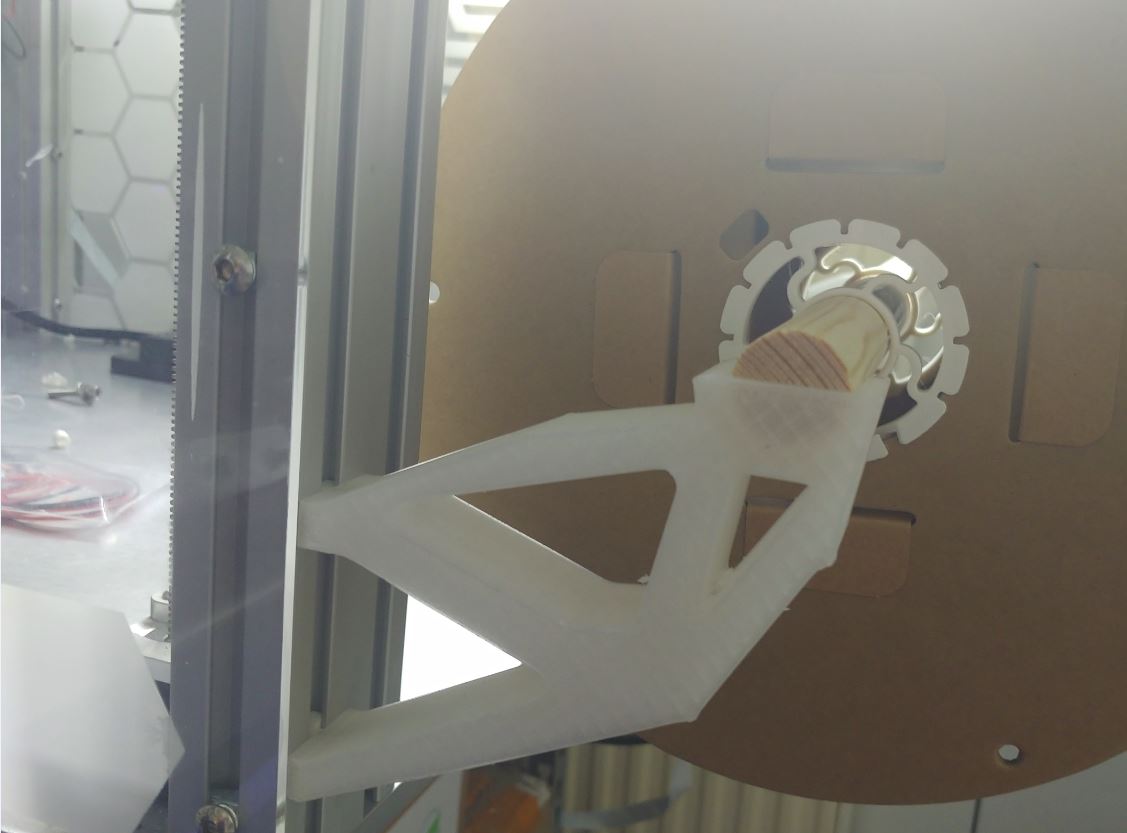
This particular holder is a filament spool holder designed to be loaded with up to 5.5kg of filament (1x2.5kg, 3x1kg).
In a broader picture: See it as a demonstration of what all those nice tools in the CAD package can do. In this application with a little bit of thought could come up with a similar or better solution but for an I don’t care design approach the output is already good. A proper design approach would be putting thought in in where to place the contact surfaces relative to the spool and then run this software or go a step further and allow a different software to also change that parameter. Keep in mind those simulations are computationally expensive. Complex/advanced questions might take days to solve while a simple question like this is less than 1 minute.
The load was in the circle/groove facing down.
The other constrain was the faces contacting the 3030 extrusion being fixed and a keep-out zone was defined around those to ensure no material there was removed.
Otherwise, it was just a flat slab as shape.
What at first surprised me was how this part works: There is a point defined by the lowest/left triangle (tension & compression) on which all the weight rests. The remaining structure is is a cross beam (top mounting point to spool) to support it (tension) and the structure on which the spool rests (compression).